
MULTI-MATERIAL PLIERS
The goal of this project was to design and fabricate pliers that can pickup through-hole resistors reliably (very small things). The pliers had to return to the open position when not compressed and be 3D printed either as print-in-place design or as a three-part hand-press assembly (assembled wihtout without tools).

What is Print in Place?
A print-in-place model is a 3D printed model made up of seperate parts that interact mechanically that can be printed in one continuous print. Moving and interlocking parts in print-in-place models are designed with clearances that allow the model to function as a whole without any post processing. Print-in-place models can be combined with multi material printing to combnine flexible hinges and joints with rigid frames. A major benefit to print-in-place is the simplicity of assembly (or lack of assembly at all) and not having to deal with exterior fasteners. However, print-in-place can make 3D printing a bit more complicated due to the tight tolerances it requires. It is easy to ruin the functionality of print-in-place models from overextrusion or dimensional inaccuracies.
Multi Material + Print-in-Place
A combination of different materials makes lots of sense for print-in-place designs as different material properities can help determine final mechanical movements of a print-in-place model. Rigid plastics like PLA and ABS can be used for the body or frame for the structure of a part while flexible plastics like TPU can serve as joints or hinges for movement.
Design
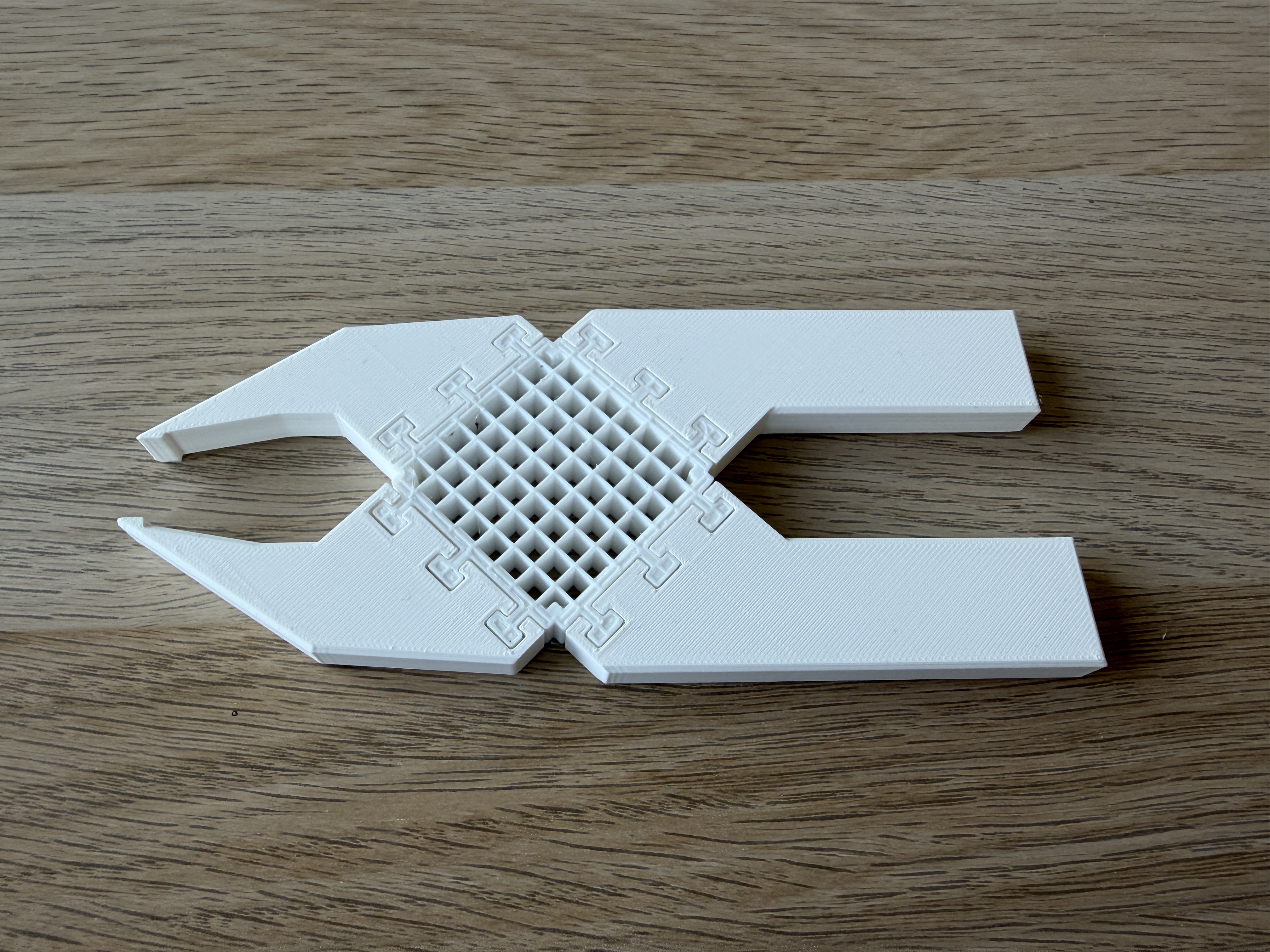
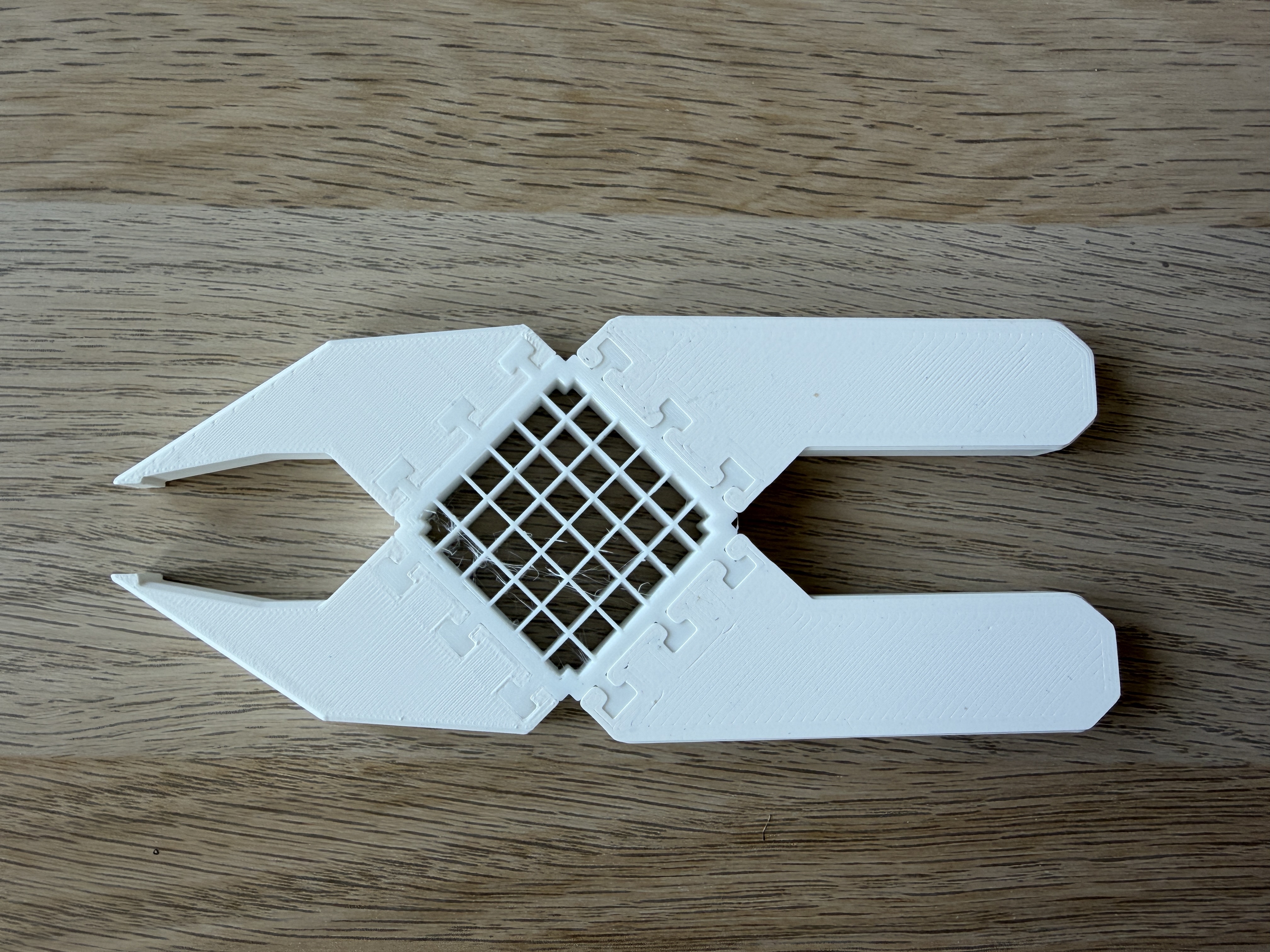
The central spring is a flexible joint of TPU that connects handles and jaws made out of rigid PLA. The TPU joint was printed with a grid infill pattern and no top or bottom walls to flex under compression and return to its neutral position when released. The joint is connected to the handles/jaws by dovetail-like joinery that allow for easy assembly and a secure fit during use. Early iterations in CAD focused on refining the geometry of the dovetail joinery, specifically the number, spacing, and angle of dovetails. I started with classic dovetail geometry and later shifted to a more squared off version. I had to print the flexible joint and jaws twice and the handles three times to dial in the correct fitment of the joinery and flexibility.
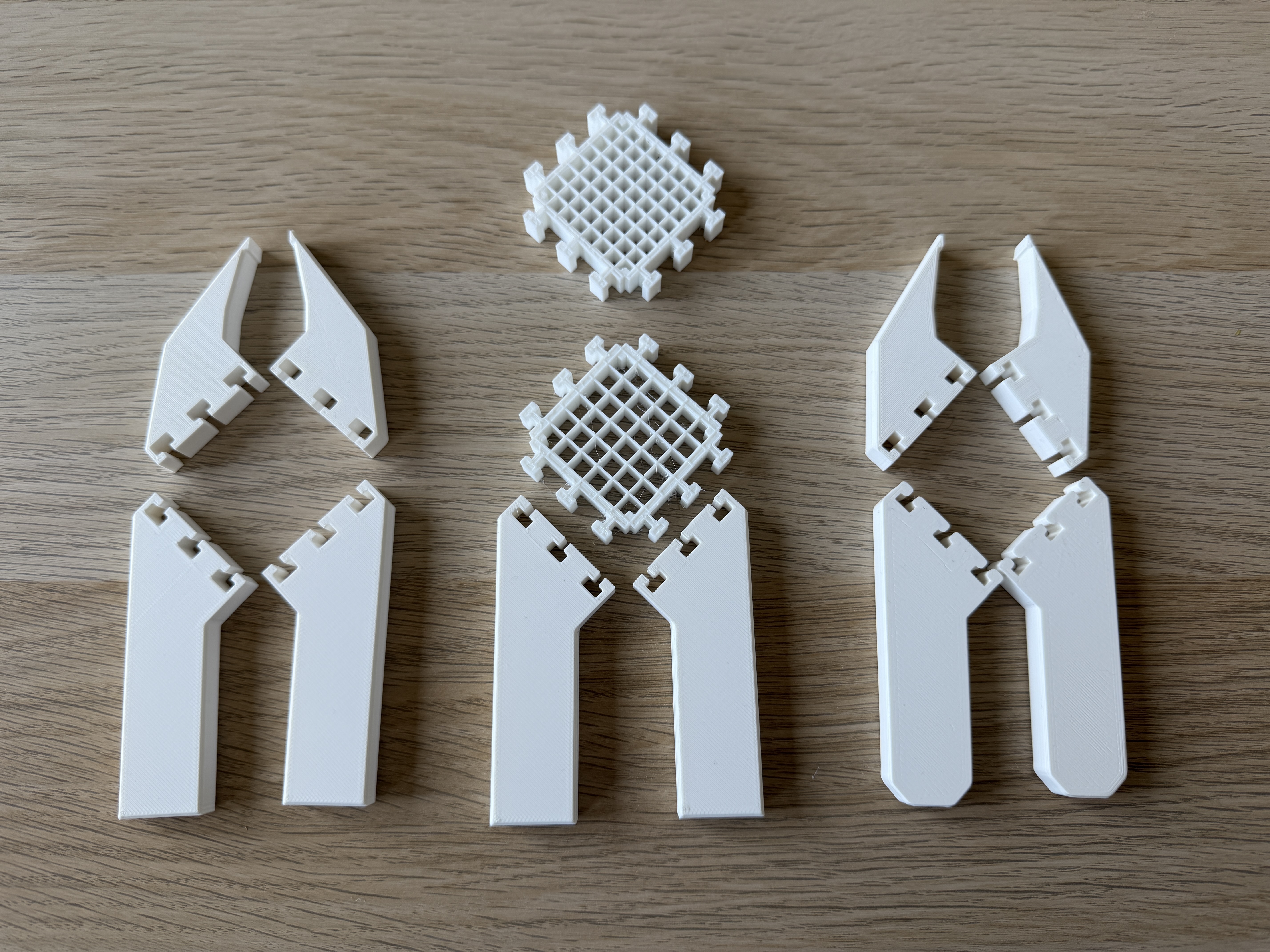
Total Printed Parts
First Iteration
I started my prototyping process using a 0.25mm offset around the dovetail joinery to allow for clearance so the parts could fit together easily. This turned out to be too much and the handles and jaws were not secured to the joint.
The first iteration of the TPU joint used a 23% infill from Superslicer. Though the handles were not secure, I could tell it was a bit stiff and felt a little difficult to actuate. The height of the pliers was 10mm and this felt appropriate for picking up resistors, which are very small. Any taller and I think the difficulty of picking up the resistors would greatly increase.
Second Iteration
Removing the clearance offset proved to provide a secure fit between the TPU joint and handles and jaws. I lessened the infill percetage of the TPU joint to 18% and this felt much better. With the jaws having full range of movement now, I could see one further problem: the inside corners of the handles were colliding with each other before the tips of the jaws, slightly restricting the range of movement
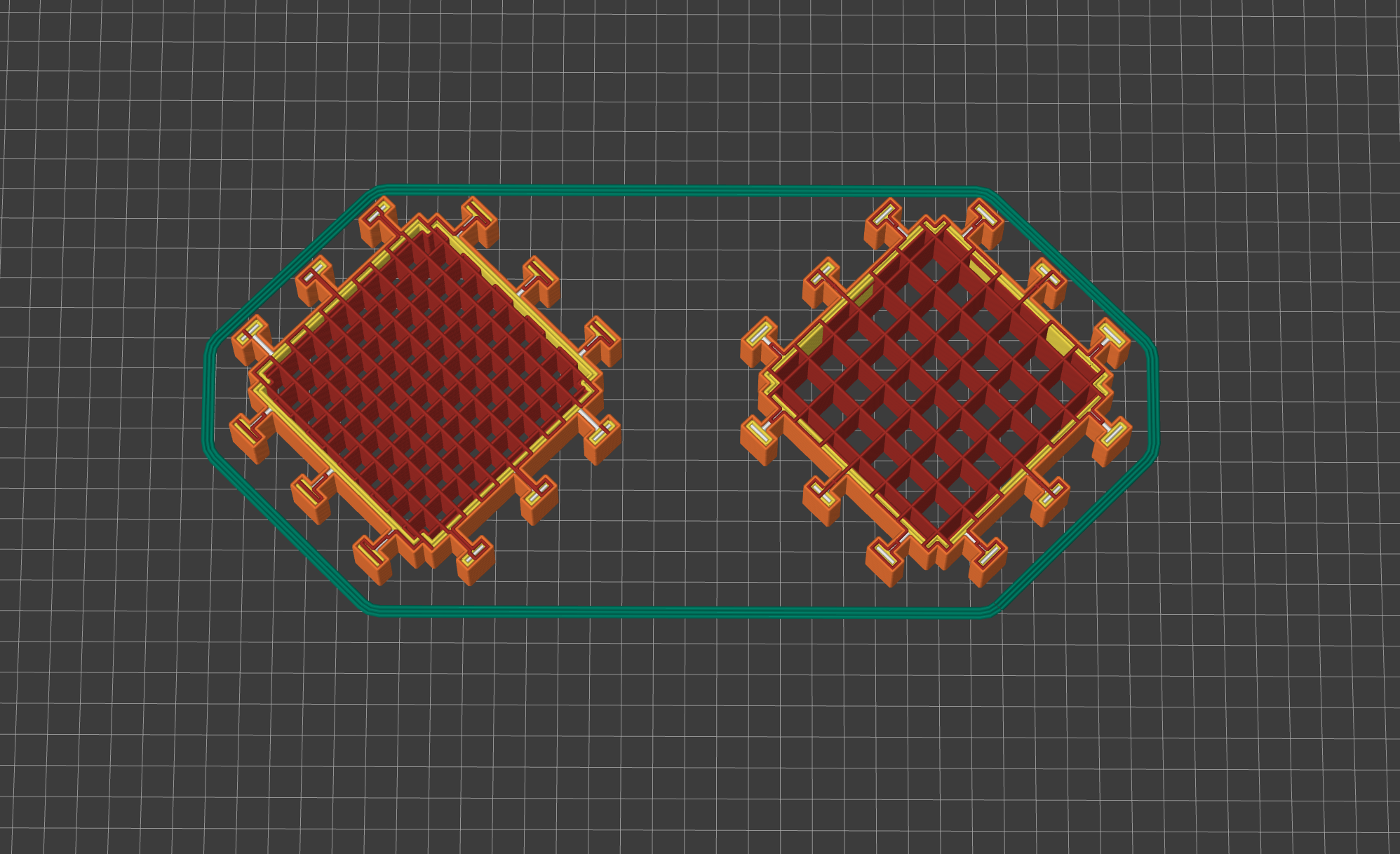

23% infill shown on left and 18% infill shown on right
Third Iteration
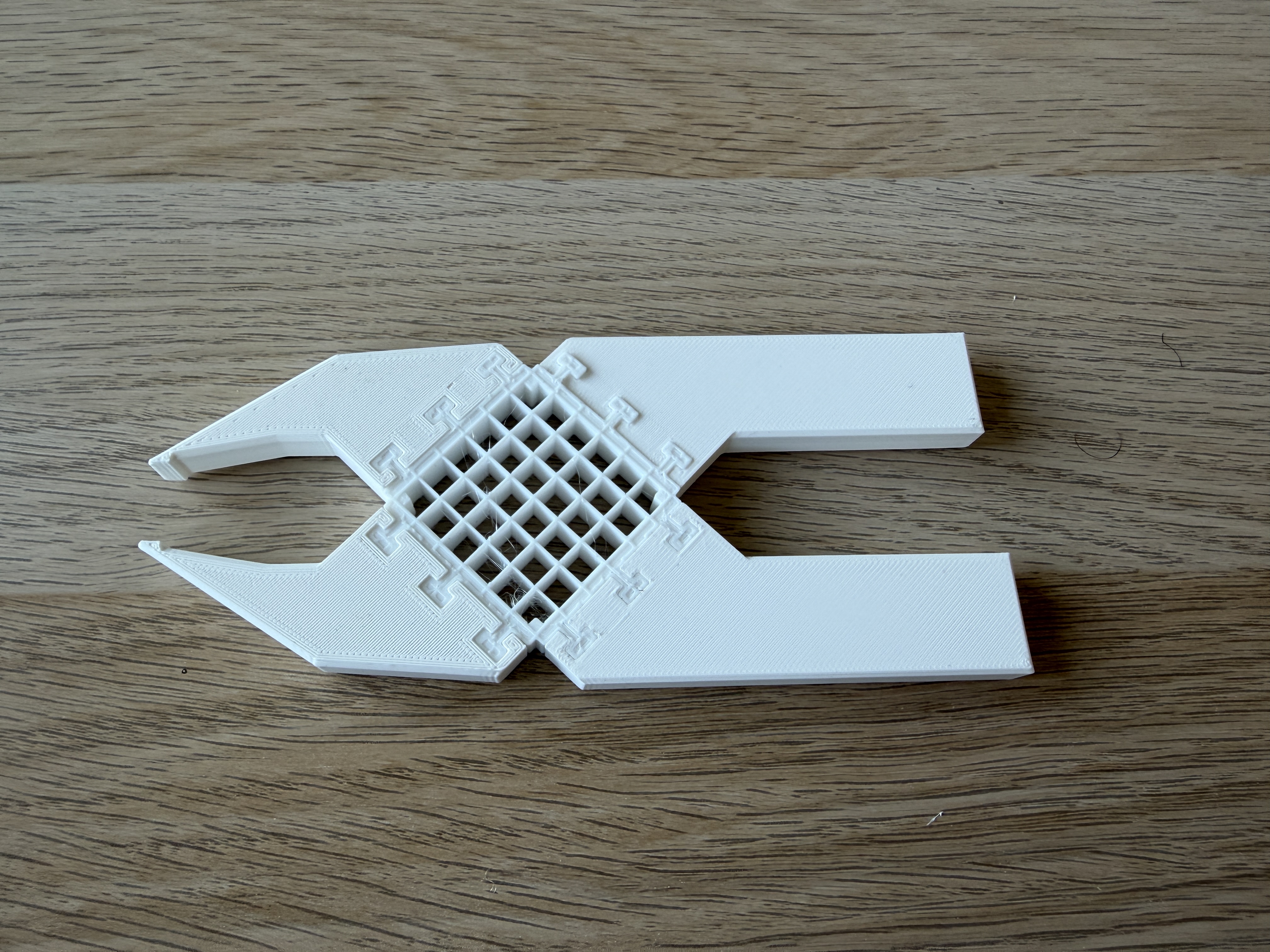
To correct the range of movement from the second iteration, I cut back the corners of the handles to allow for more travel. The pliers now fully close.